BWR Simulator
BOILING WATER REACTOR
SIMULATOR
The purpose of the 1300 MW(e) boiling water reactor NPP simulator is
educational — to provide a teaching tool for university professors and engineers
involved in teaching topics in nuclear energy. As well, nuclear engineers,
scientists and teachers in the nuclear industry may find this simulator useful
in broadening their understanding of BWR NPP dynamics and transients and power
plant dynamics. As such, the BWR simulator is used at the IAEA Workshop: NPP
Simulators for Education.
The simulator can be executed on a personal computer (PC), to operate in real
time, and to have a dynamic response with sufficient fidelity to provide BWR
plant responses during normal operations and accident situations. It also has a
user-machine interface that mimics the actual control panel instrumentation,
including the plant display system, and more importantly, allows user’s
interactions with the simulator during the operation of the simulated BWR plant.
The current simulator configuration of the simulator is able to respond to the
operating conditions normally encountered in power plant operations, as well as
to many numerous malfunctions, as summarized in the following table.
| System |
Simulation Scope |
Display Pages |
Operator Controls |
Malfunctions |
REACTOR
CORE |
-
Neutron flux levels over a range of 0.001 to 110%
full power, 6 delayed neutron groups.
-
Decay heat (3 groups).
-
Reactivity feedback effects - void,
xenon, fuel temperature, moderator temperature.
-
2 phase flow & heat transfer.
-
Reactivity control rods.
-
Essential control loops - Reactor Pressure Control;
Core Recirculation Flow Control; Reactor Power Regulation; Reactor
Water Level Control; Turbine Load/Frequency Control.
|
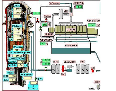
Plant Overview
BWR Reactivity & Setpoints
BWR Power /Flow Map & Controls
|
* Reactor power and rate of change (input to
control computer)
* Manual control of control rods
* Reactor scram
* Manual Control Rods “run-in”
* Manual control of core recirculation flow rate
* Manual adjustment of reactor water control level setpoint
|
* Increasing and decreasing core
flow due to Flow Control malfunctions
*Inadvertent withdrawal of one bank of control rods
*Inadvertent insertion of one bank of control rods
*Inadvertent reactor isolation
*Power loss to 3 Reactor Internal Pumps (RIPs)
*Reactor bottom break
|
|
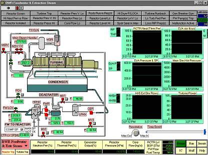
STEAM & FEED-WATER |
- Steam supply to turbine and reheater.
- Main Steam Isolation Valve.
- Turbine Bypass to condenser.
- Steam Relief Valves to Suppression Pool in containment.
- Extraction steam to feed heating.
- Feedwater system.
|
BWR Feedwater and Extraction Steam |
* Reactor water level setpoint changes: computer or
manual
* Extraction steam to feedwater heating isolating valves controls
* Deaerator main steam extraction pressure control
* Feed pump on/off controls
|
*Loss of both feedwater pumps
* Loss of feedwater heating
* Reactor feedwater level control valve fails open
* Safety valves on one main steam line fail open
* Steam line break inside Drywell
* Feedwater line break inside Drywell
|
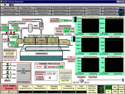
| TURBINE-GENERATOR |
|
BWR Turbine-Generator |
* Turbine trip
* Turbine run-back
* Turbine run-up and synchronization
* Turbine Speeder Gear control: manual or computer control
* Steam Bypass Valve Computer or Manual Control
|
* Turbine throttle pressure transmitter fails low
* Turbine trip with Bypass Valve failed closed
* Increasing and decreasing steam flow due to Pressure Control System
failures |
|
OVERALL UNIT |
- Fully dynamic interaction between all simulated systems.
- Turbine-Following-Reactor load maneuvering.
- Unit annunciation.
- Major control loops.
|
BWR Plant Overview
BWR Reactivity & Setpoints
|
|
|
The interaction between the user and the simulator is via a combination of
monitor displays, mouse and keyboard. Parameter monitoring and plant operator
controls, implemented via the plant display system at the generating station
,are represented in a virtually identical manner on the simulator. Control panel
instruments and control devices, such as push-buttons and hand-switches, are
shown as stylized pictures, and are operated via special pop-up menus and dialog
boxes in response to user inputs.
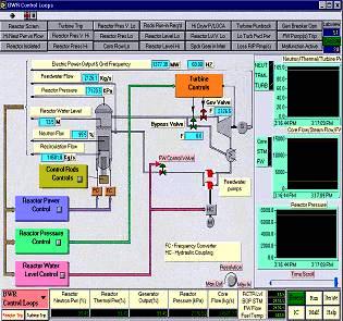
BWR Control Loops Screen
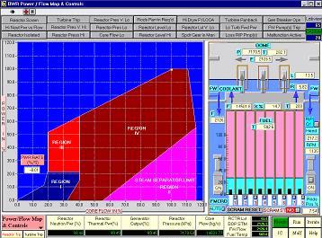
BWR Flow Map & Control Screen
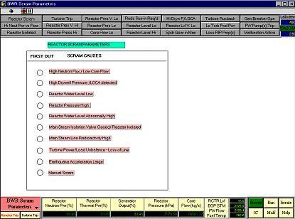
BWR Scram Parameters
BWR Turbine Generator
BWR Feedwater & Extraction Steam

|
 CTI SIMULATION
INTERNATIONAL
CTI SIMULATION
INTERNATIONAL